-
If the Methven Kiri Satinjet uses so little water how will I have a proper shower? How is it better than other low flow shower heads?
Older low flow shower heads simply restrict the flow of water coming out of your shower, this has lead some people to believe that all low flow shower heads are the same and produce an inferior shower experience. It is important to note that the Methven Kiri Satinjet uses completely different technology to a normal shower.
What technology you might ask?
As the name suggests the technology is called Satinjet. Satinjet technology is based on the Venturi effect, where air is sucked in to the shower head through special breather holes to create large droplets of an air/water mixture with maximum surface area for minimum volume. The Satinjet head produces 150,000 of these droplets per minute.
So instead of most of the warm water simply flowing off your skin without imparting any warmth, as it does in a normal shower, the Satinjet covers your skin in a warm cloud of smaller droplets imparting maximum warmth to you even though the flow of water is much less than a regular shower. In short the Methven Kiri Satinjet is much better and more efficient than a regular shower head, which has to drench you in water to get the same warming effect.
-
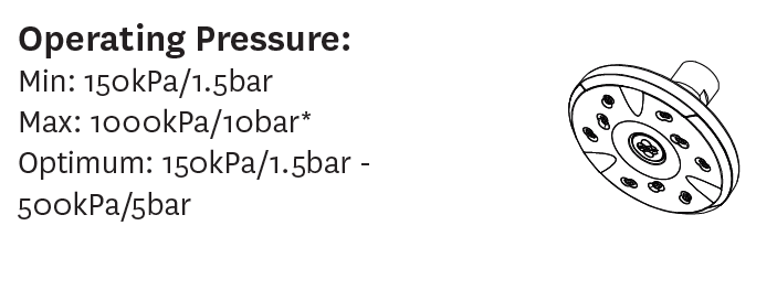
What is the lowest pressure the Methven Kiri Satinjet ultra low flow shower head can operate at?
The optimum operating pressure for the Methven Kiri Satinjet is 500kPa / 5bar. However the showerhead can operate as low as 150kPa / 1.5bar. Giving you plenty of flexibility.
-
How to find error codes on my Daikin Alira X?
If you believe your Daikin Alira X heat pump heating/cooling air conditioner is malfunctioning, you can check for any error codes via the Daikin remote controller.
This is recommended before raising a service case with Daikin and can help speed up any fault diagnosis.
Here are the steps to check for any error codes:
- Find the "Cancel" button (bottom left when you slide down the front of the remote controller), press and hold for approximately 5 secons, "00" will blink in the temperature display section
- While the "00" is blinking, press the same "Cancel" button repeatedly until a long beep is hear. At this point the code indication will change.
Some notes:
- If you hear a short beep and two (2) consecutive beeps this indicates a non-corresponding code.
- To cancel the code display, you hold the "Cancel" button down for approximately 5 seconds. Alternatively if no button is pressed for one (1) minute the code display will clear.
-
How do I set up the Daikin Alira X monitoring?
For setting up your Daikin Alira X heating/cooling mobile app.
Where will you be able to view your monitoring? Mobile/Tablet App "Daikin" - Android or Apple App Store
Daikin Alira X excerpt from the Operation Manual for LAN for set up you can view on our website -> https://pure-electric.com.au/resources/daikin-alira-x-wireless-configuration
-
Are STC rebates available for an off-grid solar setup?
Yes, STC rebates are available where you have a Fronius SCERT inverter coupled with a Selectronic SP Pro micro-grid. This is a standard solution we offer.
-
How much does it cost to go off-grid?
The cost to go off-grid will depend on your expected/anticipated energy demand. With knowledge of your energy demand we can then help you size your battery storage, solar PV, generator, microgrid inverter, etc.
It is worth noting that connecting a new block to the power grid can cost between $15,000 and $50,000 depending on the situation. And a typical energy bill for the average household is around $3000-$4000 per year (or higher in colder areas). Given the cost of grid connection and supply, a well maintained and high quality off-grid system is likely to be cheaper in the long run (20 years +), depending on your particular situation (if grid connection is >$30,000 you can pretty much assume off-grid will be cheaper).
-
What size solar PV do I need for my off-grid?
You want as large a rooftop solar PV system as you can fit on your roof to reduce the amount of time you need to rely on your backup generator that may be required for periods during winter periods or times of low solar radiation (i.e. multiple cloudy days).
We generally recommend a minimum 10kW solar PV system, but the final size will depend on your anticipated load/demand. We can help you work this out by using our load profile sheet as part of our comprehensive quoting process.
-
Do I need a generator for my off-grid system?
Your solar system should cover your power needs 95% + of the time, however we highly recommend a good quality, automatic start generator to ensure you have energy security and full power capacity throughout the worst days of winter.
-
Selectronic SP PRO and SP LINK Firmware Updating
You have a Selectronic SP PRO Series 2i Inverter and would like to ensure you keep the Firmware up to date?
- Ensure you have the Latest SP LINK Software downloaded. This is critical to ensuring the latest Firmware gets loaded onto the SP PRO.
- Go to the Selectronic website here to download the latest SP LINK version
- Open SP LINK on your Windows PC and confirm you have the latest SP LINK installed - you can go to "Help" -> "Check for Updates")
- In SP LINK go to "File" then go to "Firmware Update..."
- If an SP PRO Firmware Update has been detected, click the button, "Update Firmware and Restart SP PRO on completion"
- During the SP PRO restart, "the SP PRO may be inaccessible for a few minutes while the firmware is installing. During this time, the SP PRO alarm may sound."
- Once uploaded and restarted - your SP PRO should now have the latest Firmware and will say, "The firmware is already up to date."
NB: The Selectronic website for a full history of the Selectronic SP LINK and SP PRO software and firmware updates
-
Myenergi Hub How do I update the firmware?
You can view your Myenergi Zappi EV charger basic controls and data on the Myenergi Hub.
If you would like to update your Myenergi Hub to the latest firmware, some details for how to update this:
The Myenergi Hub has two buttons. The steps to update the firmware:
- Unplug Power to the hub
- Press and hold the 'Download' button (right hand side)
- Keep pressing the 'Download' button while you plug the power back into the hub
- Check the status lights on the Hub – once the Power LED turns yellow, release the button
- The Power LED light should be Green and the Server LED light should be white while the firmware is downloading
- Once the download is complete the Server LED light will turn green (or blue) again
info@pure-electric.com.au
1300 86 78 73